|
Mainland High School
Cutting the Cord: ISTF 07-1726 |
||||||||
|
Home
Introduction Components One Two  Product Product
Three Microwave Research W. C. Brown Generators History Phased Arrays Properties Rectennas Semiconductors Solar Satellites Superconductors Moon Research Colonization Helium-3 Fusion Geography Mining Resources Project Assessment Bibliography Glossary Team |
Microwave Generators
There are several forms of transmitting energy that do not depend on electrical wires besides the use of electromagnetic radiation, or in our case, microwaves. However, these methods are inapplicable due to the vast distance between the Earth and the moon and the lack of matter between the two celestial bodies.
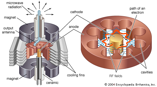
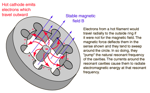
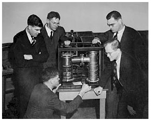
Electromagnetic induction is one form of wireless power transmission. The primary and secondary circuits of a transformer are isolated. A process known as induction couples the two circuits allowing power to pass through. This is used in induction cookers and electric toothbrush chargers. This method cannot be used to beam energy from the moon due to its very short range. Another method used is electrical conduction. This involves sending a current through the Earth itself, with a surprising amount of efficiency. This is also useless because the power is being sent from the moon to the Earth and not from one place on Earth to another. The final method of wireless power transmission is evanescent wave coupling. This involves creating an environment where the electromagnetic waves carrying the energy are extremely likely to tunnel, and pass completely unaffected through the medium. However this is also irrelevant due to the lack of matter in the vacuum of space between the Earth and the moon and its limited range. Magnetrons Magnetrons are devices capable of creating high energy electromagnetic microwave radiation. A. W. Hull first investigated their behavior in 1921. They are composed of a hollow tube with a filament in the middle. The outer part of the tube acts as an anode while the filament is the cathode. When this filament is heated it releases electrons, which try to travel to the positive anodes on the outer tube. However, an external magnetic field passing through the tube keeps the electrons from reaching the anodes and forces them to move in circles around the cavities in the tube. This creates radiation at the resonance frequence of the tube. Klystrons The klystron was developed at Stanford in the 1930ís as a response for the need of a high power, high frequency microwave generator needed for radar and navigation of aircraft. It was invented by Russell and Sigurd Varian under the mentorship of Professor Bill Hansen.
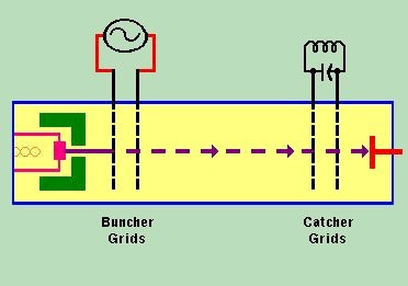
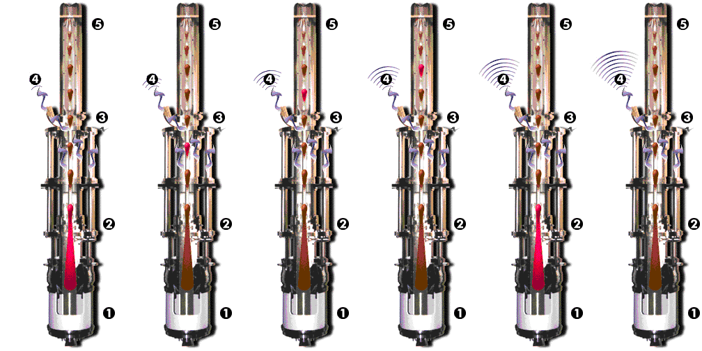
The klystron uses the resonating tube to cluster electrons together in wave-like groups. The pseudo-Greek word klystron comes from κλυσ- (klys) of a Greek verb referring to the action of waves breaking against a shore, and the end of the word electron.
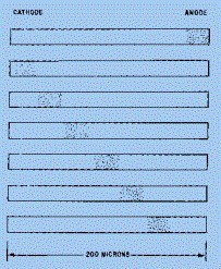
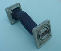
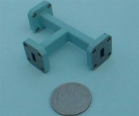
The following model was used in conjunction with a particle accelerator. Note: the descriptions begin at the bottom and work up. Semiconductors - The Gunn Effect In 1963, J. B. Gunn discovered that microwaves could be generated through a semiconductor material by applying a steady voltage across it. This transferred-electron effect is created by raising the electrons to conduction-band energy levels higher than those they usually occupy. A Gunn Oscillator can supply continuous power up to 65 milliwatts of power, at will pulsed outputs as high as 200 watts. There are many types of semiconductors used for microwave transmission but GaAs (gallium arsenide) is the metal generally used. Gallium arsinide, indium phosphide, and silicon are semi-conductors that can be used for the amplification of microwaves. By applying increasing amounts of voltage to the semiconductor chip, varying electric fields are created. There is an electric field called the domain which has a much higher intensity than the rest. The domain travels across the semiconductor chip from the cathode to the annode. Below is a demonstration of this happening, the bunch of dots is the domain. Semiconductor/Superconductor Hybrids Semiconductor/superconductor hybrids, are designed for cryogenic applications. The superconductor allows for high power to flow with low power consumption and conversion loss. The semiconductor part helps keep the temperatures within operable ranges. NASA approved these semiconductor/superconductor hybrids for the extreme environment of space. When a current is passed through a semiconductor it can create electromagnetic waves, or microwaves, which J. Gunn discovered in 1963. Semiconductors can also be used as amplifiers for microwaves. A tunable nanoscale superconductor/semiconductor hybrid device has been created with indium arsenide semiconductor nanowires individually contacted by aluminum-based superconductor electrodes. WaveGuides A waveguide is a device designed to retain and guide electromagnetic waves to a specific place where they are in turn transmitted. Waveguides are enclosed tubes which block out adjacent signals and allow them to transmit microwaves at high peak powers with a negligible loss of power. The disadvantages of waveguides is their cost and weight. Copper and silver are used in waveguides and are relatively expensive. A short-slot waveguide is basically a coupler that equally splits the power perpendicular to each other.
Encyclopedia Brittanica Online - Magnetron: typical elements http://www.britannica.com/eb/art-137/Typical-elements-of-a-magnetron Fast Neutron Research Facility - Bulk Effect Semiconductors http://www.fnrf.science.cmu.ac.th/theory/microwave/Microwave%2014.html Google Patent Search - United States Patent: 3434678 http://www.google.com/patents?id=DdQXAAAAEBAJ&printsec=abstract&zoom=4&dq=5986506 HyperPhysics - Magnetron Operation http://hyperphysics.phy-astr.gsu.edu/hbase/waves/magnetron.html JPL/NASA Lewis Research Center - Space Qualified Hybrid Superconducting / Semiconducting Low-Noise Downconverter http://trs-new.jpl.nasa.gov/dspace/bitstream/2014/24336/1/96-0364.pdf (pg 2) Microwave Electronics - Microwave Vacuum Devices & Maser http://www.isi-soft.com/docs/Books/Book21/Ch2_1.pdf (pg 4) Microwaves101 - MMIC semiconductor tradeoffs http://www.microwaves101.com/encyclopedia/MMICsemi.cfm#inphemt Microwaves101 - Short-Slot Waveguide Hybrid http://www.microwaves101.com/encyclopedia/short-slot_hybrid.cfm Microwaves101 - Waveguide primer http://www.microwaves101.com/encyclopedia/waveguide.cfm PowerPedia - Wireless transmission of electricity http://peswiki.com/index.php/PowerPedia:Wireless_transmission_of_electricity#Wireless_energy_transfer_methods QuinStar Technology, Inc. - QCA Series Cryogenic Amplifiers and Systems http://www.quinstar.com/qca_cryogenically_cooled_amplifiers_and_systems.html Science Magazine - Tunable Supercurrent Through Semiconductor Nanowires http://www.sciencemag.org/cgi/content/abstract/309/5732/272 Stanford University - Department of Physics: History http://www.stanford.edu/dept/physics/history/index.html Stanford University - Klystron is a Microwave Generator http://www2.slac.stanford.edu/vvc/accelerators/klystron.html Stanford University - Klystron Tube http://www.stanford.edu/home/welcome/research/klystron.html University of Toronto - Development of the Larmor Condition http://www.physics.utoronto.ca/~phy326/esr/esrapp.htm Wisegeek - What is a Magentron? http://www.wisegeek.com/what-is-a-magnetron.htm |
|||||||
